A small build log for my last robot, a rugged tank that hopefully one day could be used in search and rescue scenarios.
More likely you’ll see it skidding in a parking lot.
Building robots is a lot of fun, it gives you the opportunity to raise your skills in electronics, crafting, software, 3d modeling, 3d printing .. the list can continue.
It can get quite expensive too, so taking some shorctuts is definitely a must, especially when it comes to reuse / repurpose / plain hack devices that can be bought cheaply due to economy of scale. So, when I watched the “How To: Moving Objects” from ccc’s Gulaschprogrammiernacht 18 (video here) I just couldn’t believe my eyes. Tearing apart an hoverboard gives you everything from a the dream list of every robot builders:
- A powerful dual motor driver
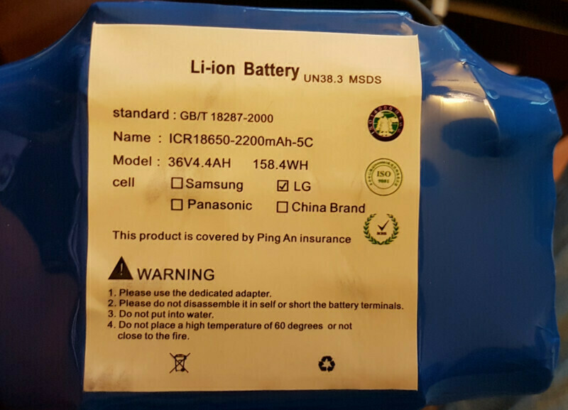
- A capable battery
- Battery charger
- Two high torque motors
- Switches, connectors, leds and whatnots
Just try to sum up all of the above from other sources and you get the idea of the price. Now try to beat the price of hoverboards, even new. Some can be bought for as low as 79e new, if you find an offer.
so I waited to get a new one and when I found an offer for 89e, the journey started.
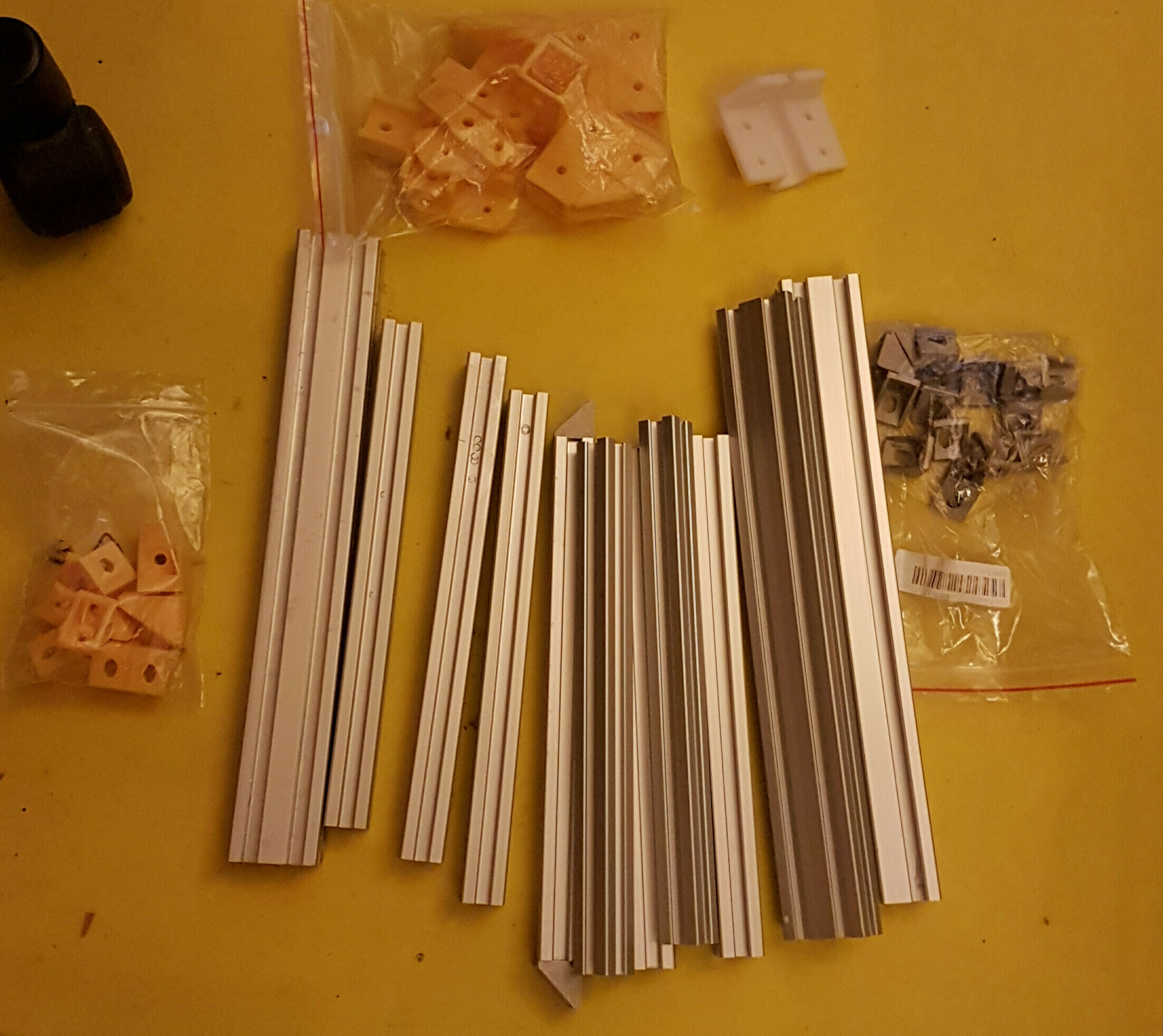
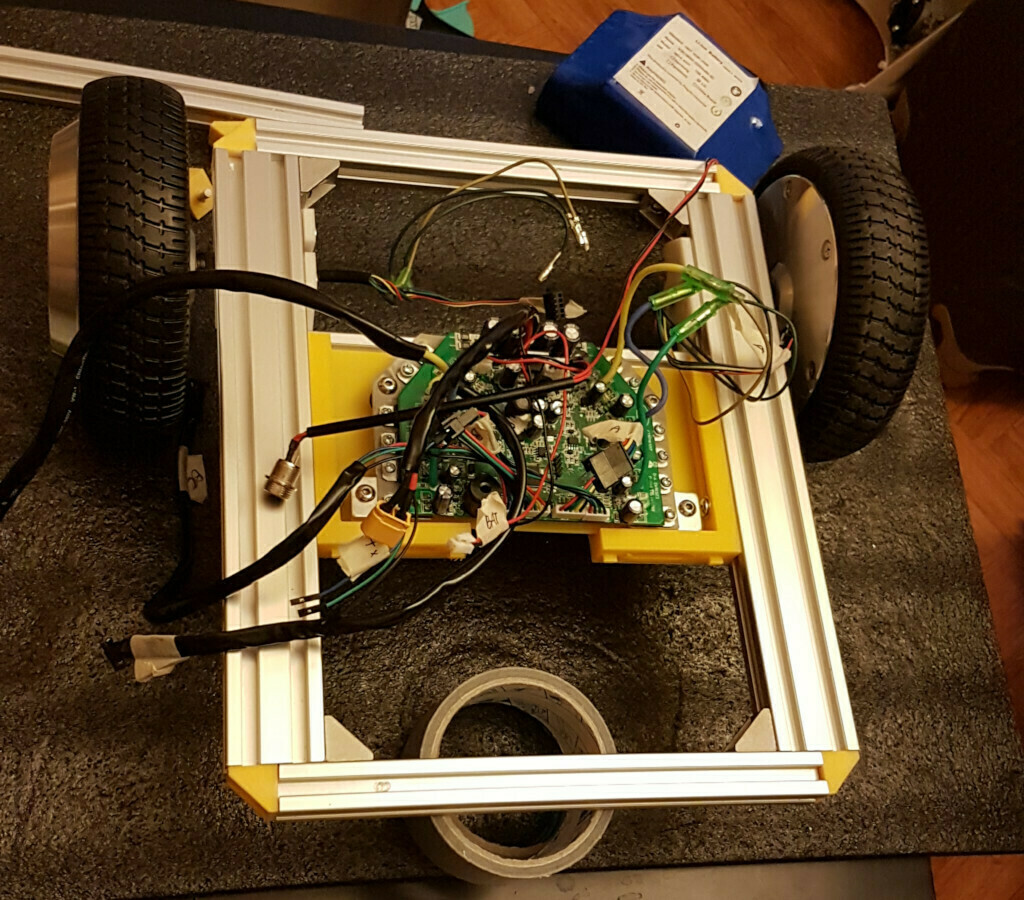
While I was waiting for the delivery, I started collecting pieces here and there. Since I had some leftover 2020 bars from another project (A custom made 3d printer, called “Ragnetto”), some 90° bracket (pla and metal ones), I challenged myself to use only these for the frame.
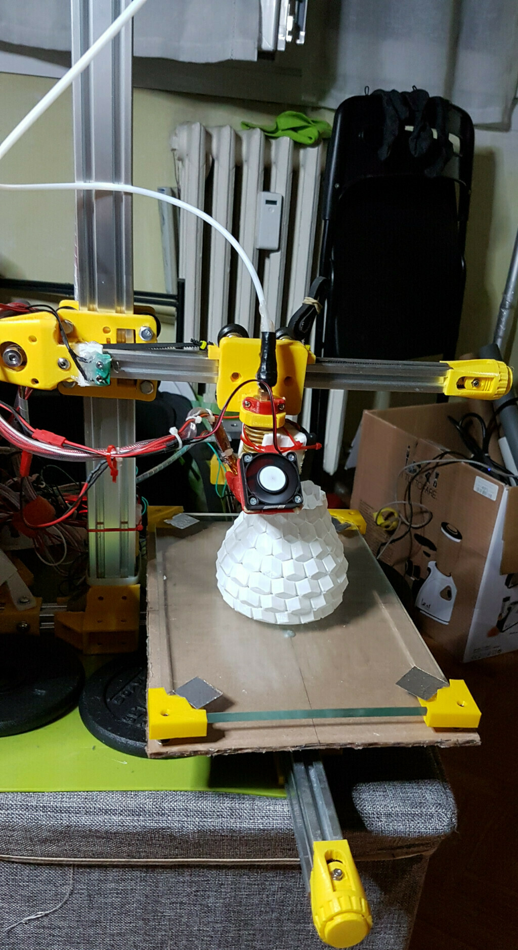
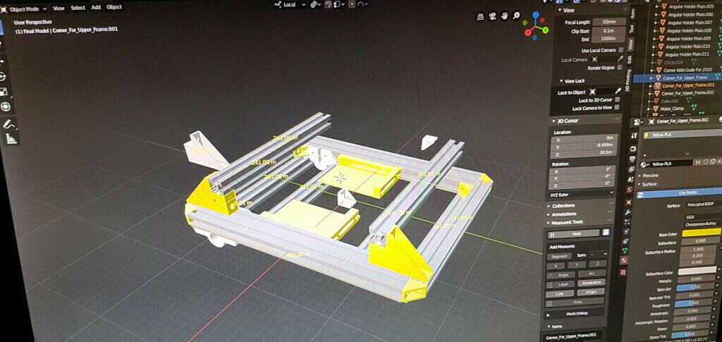
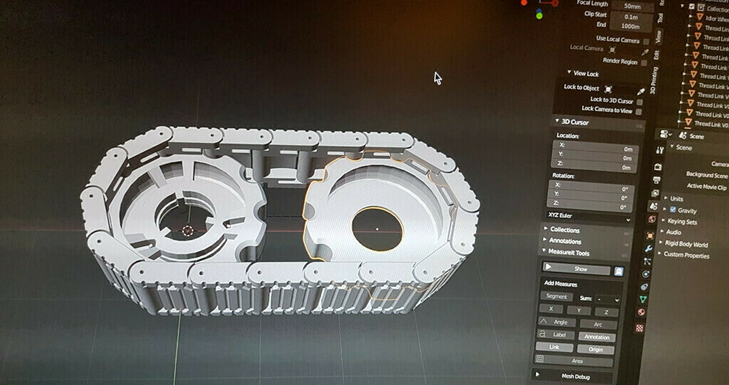
Luckily they were enough for a simple frame construction, so I started modeling the frame with Blender and also searched on Thingiverse for reference models such as motors clamp (the white one in the image), from which I started my measuring.
With measurements done for the 3d models and also by inferencing the sizes from photos found online (Gimp and Perspective tool to the rescue!), I came up with the first revision for the frame.
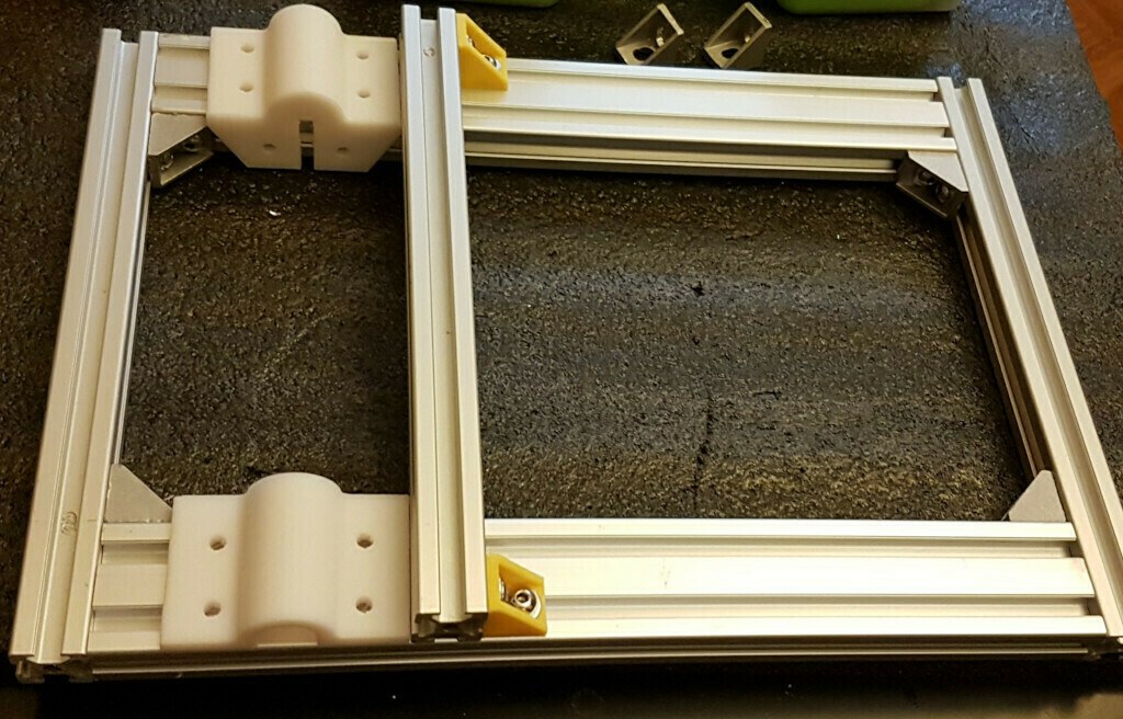
While I was testing various placements for the 2020 bars in order to maximize the rigidity (I admit it, 2020 bars are just Lego for grown kids.) the hoverboard arrived!
Since I never rode an hoverboard, I gave myself an hour or so of plain fun trying not to smash my head against walls.
Of course I just had to do it to test whether the hoverboard was not DOA..
yeah, right.
After that the real fun started.
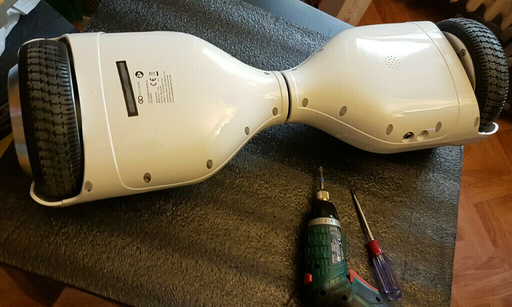
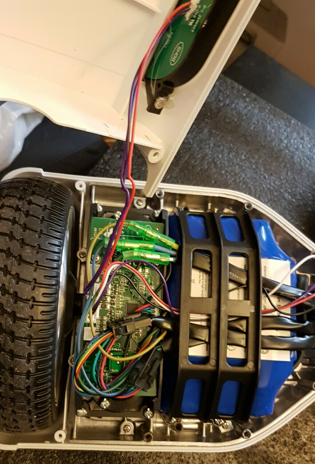
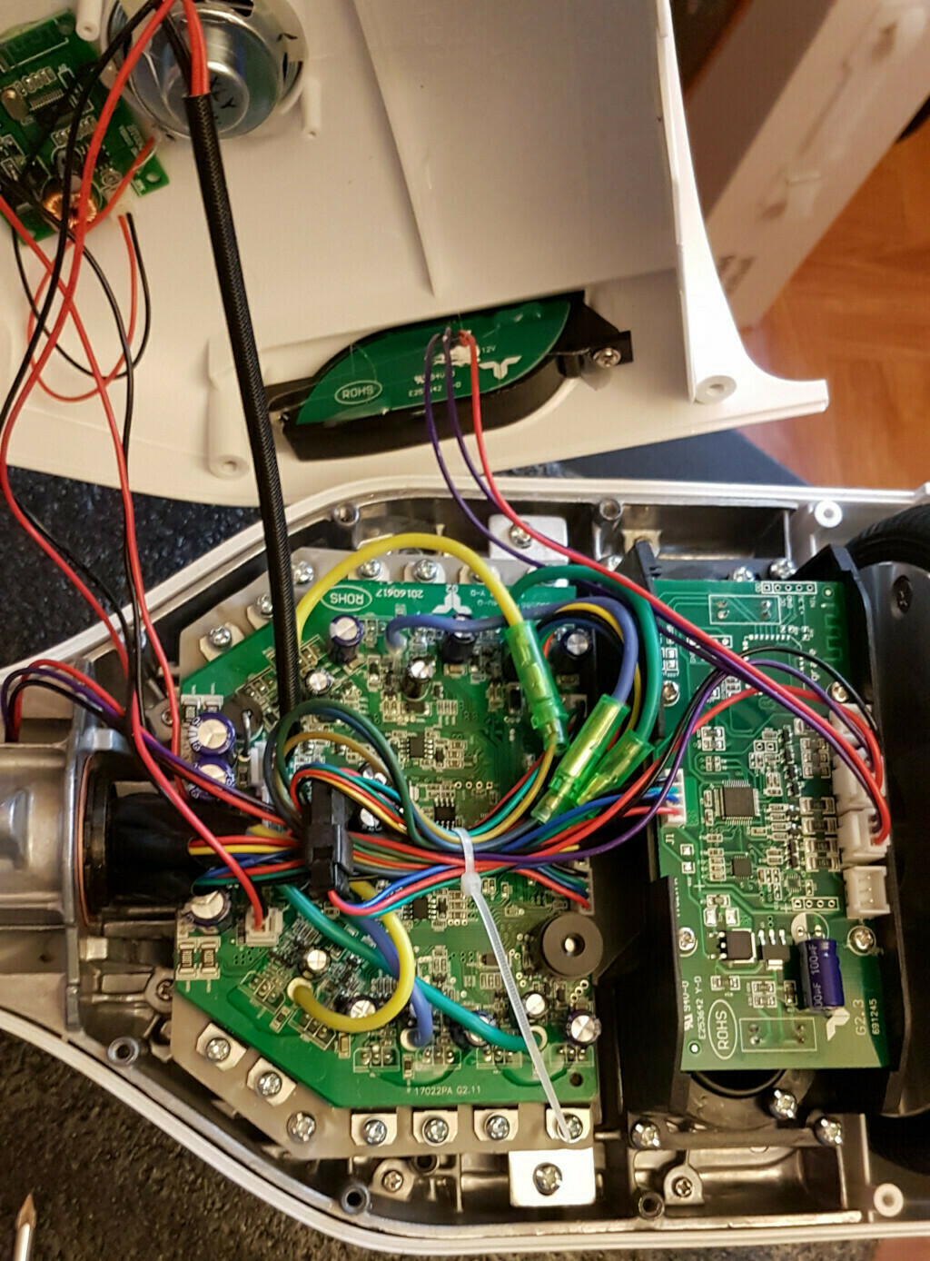
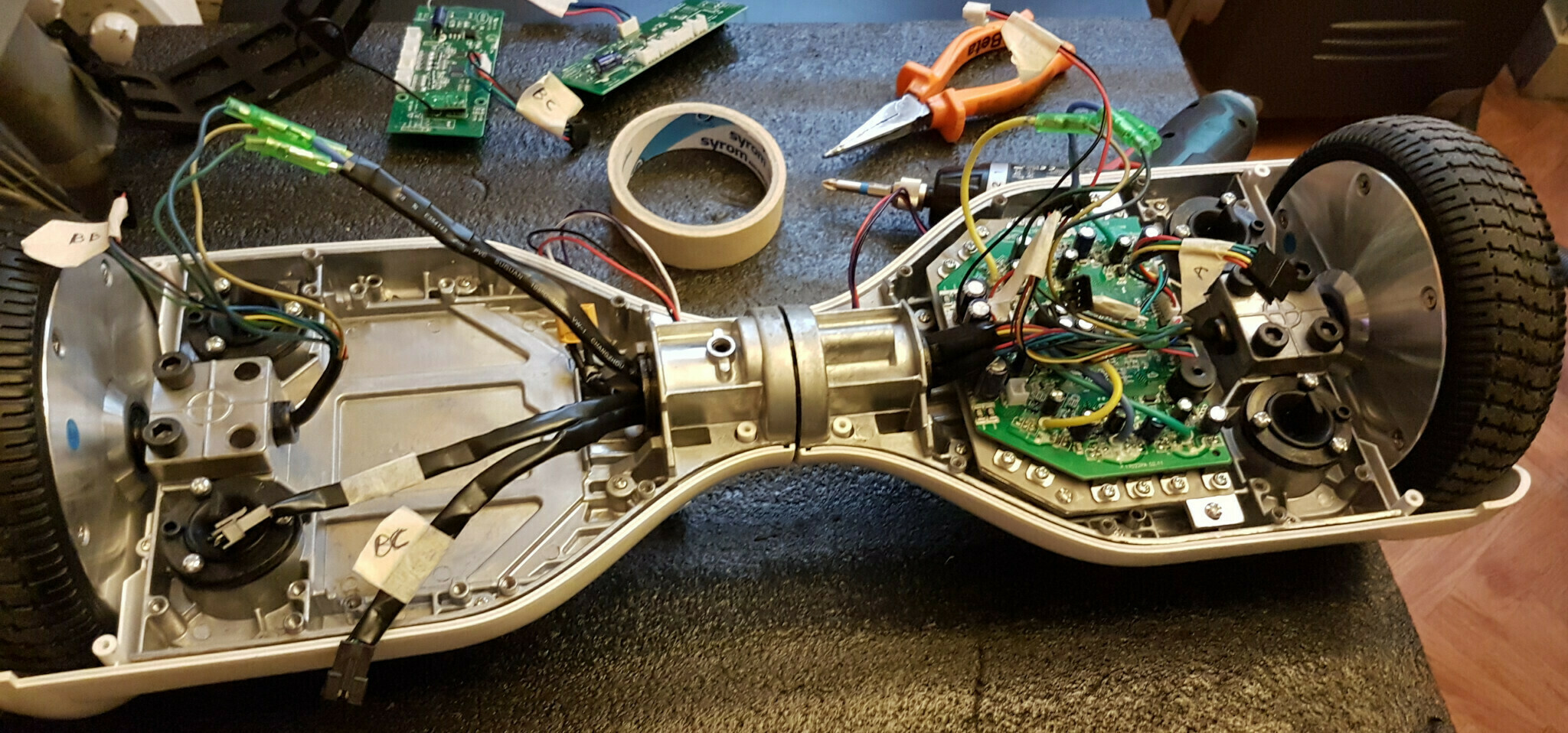
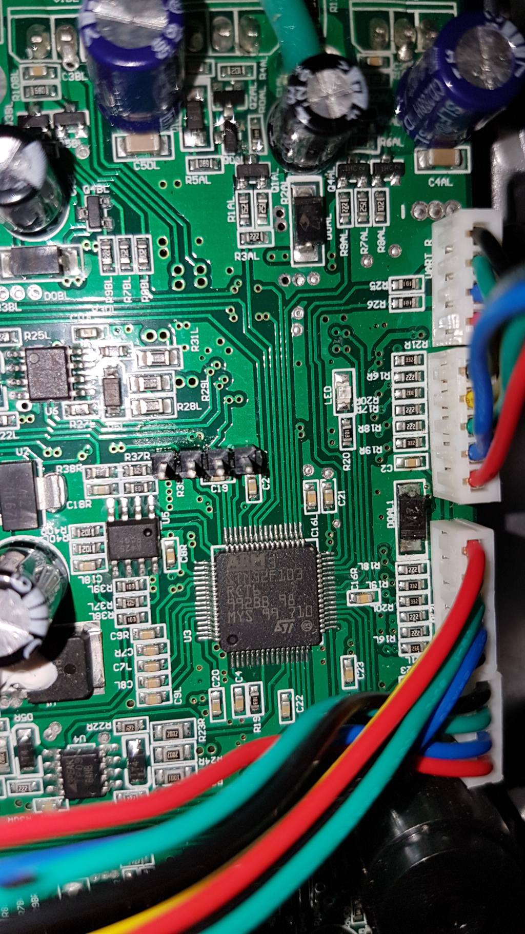
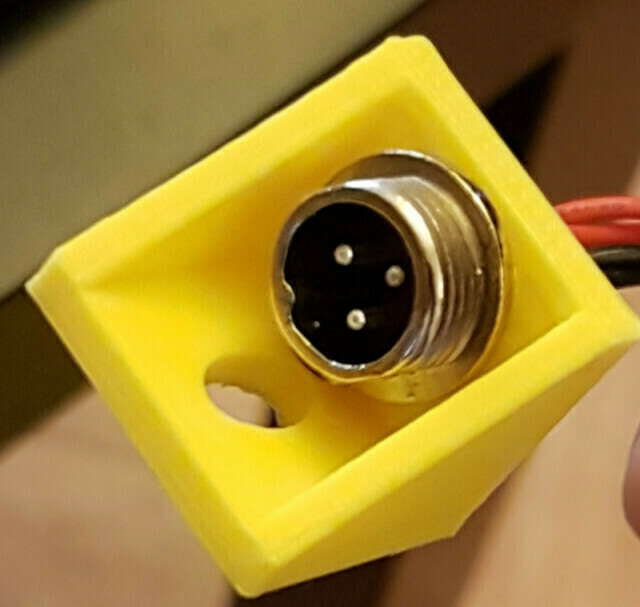
I took my time to completely disassembly the hoverboard while taking photos / notes / labeling cables, you never know what kind of reference you’ll desperately need later so .. better safe than sorry, I’ve made an abundance of photos. Meanwhile I poked with the multimeter here and there on the traces that I found of some interest. Here are some photos for you hardware-loving guys.
Next I managed to cross-compile the firmware (I tried quite a lot of them, then I found out the “Bipropellant” which had all the features I wanted), I started to test various controlling scheme, both hardware and software. I found a comfortable way to control the motors while finishing the build (I settled using the pots control method) once I confirmed that I could control the hoverboard via serial (using a Raspberry pi and a usb-to-serial adapter) I was confident enough that I could use this board for my project, then I literally dive in Blender for the following weeks modeling and printing pieces. This project was the one which took the most hours of printing, with pieces ranking up to almost 9 hours of print time, I made a schedule so I could use every spare time to start a new print job. Some pieces took way many revision to get them just right, especially the driving gear that is mounted on the hoverboard wheel. Alas, since the wheels are not perfectly round I had to enlarge the pieces in order to have a lot of space to make adjustments. I splitted the parts to print in order to make educated guess on the volume I was left with once I mounted that set of pieces. I started with the motor clamps and board mount.
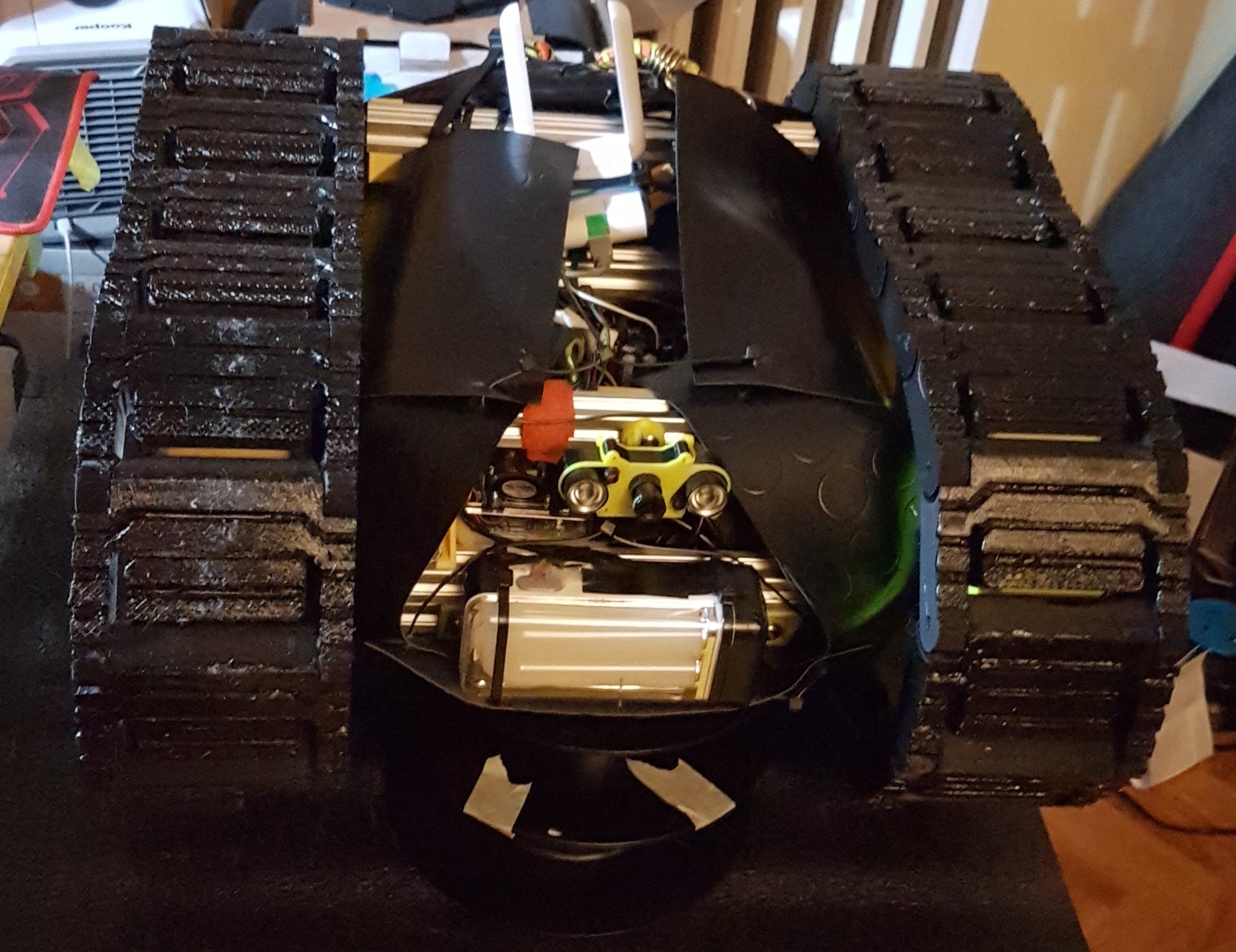
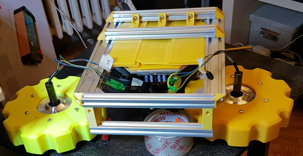
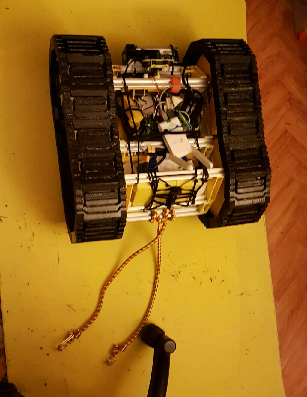
With the wheels and the board in place, it was time to address the elephant in the room, that is the battery. I needed a place which was safe from whatever dangers the little tank could face. It was also time to consider a proper weight distribution, with the major components in this regard being the wheels which houses the motors and the battery. I tried various approaches then i ended up putting most of the weight in the front so It should not flip over when climbing steep slopes. So the motors would be front-facing, the battery in the rear compartment in order to distribute a bit the weight. With that insight gained, I went back to Blender..
You might be wondering about the use of Blender as a CAD and every doubt you can come up with, you probably have a point. However I have been using Blender for years and I’m quite comfortable snapping objects, vertext, heck I even like adjusting normals myself. The degree of freedom I can feel when using Blender is unmatched by other CADs, I just feel at home, meshes have no secrets for me. (It has to do with a past life modeling things for videogames..)
If you’re interested in using Blender as a CAD i’ll leave some tips and tricks at the end.
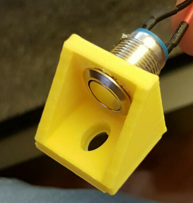
While I was wondering how to properly attach a gear to the wheel, I used the spare printing-time to print small pieces which were hard to not get right, such as these connectors, which I was quite confident I could get right at the first iteration
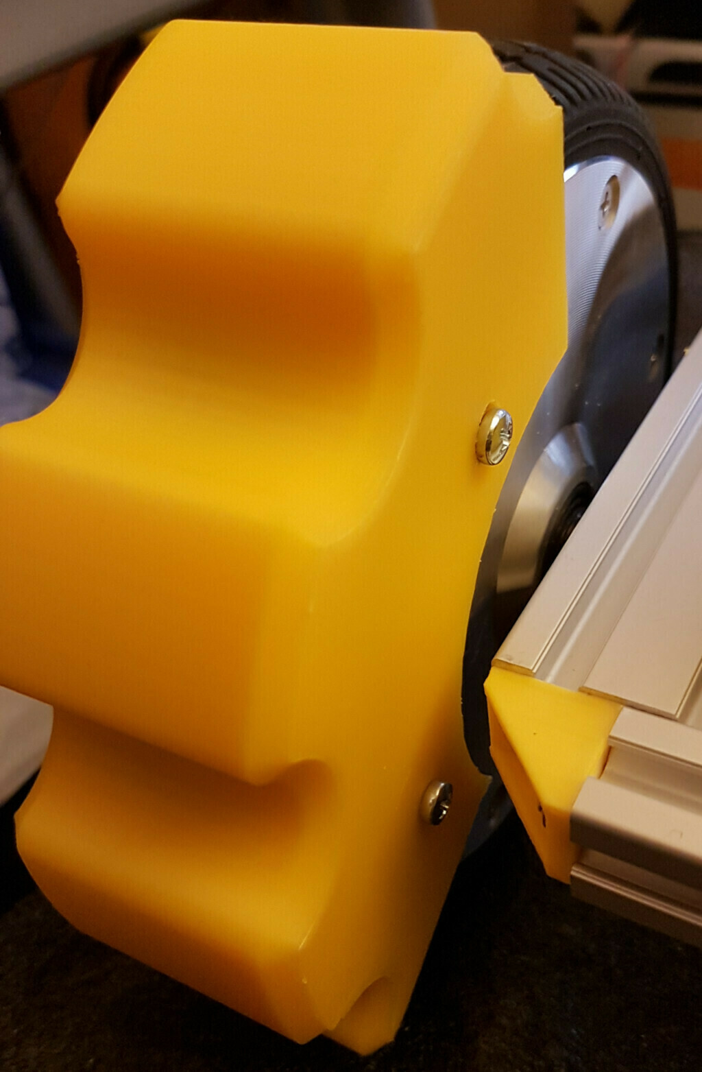
But it was time to address the elephant in the room, how to properly attach the gear to the wheels. I tought about removing the rubber coating from the wheels and to start from there, but since I print mostly in PLA and sice I noticed the motors getting hot, I had either to swap material or find a different approach. Then when I started poking around the wheels I had this idea, using the screws that held the wheel frame to attach the printed pieces in a way that would sit on top of the rubber coating, this would provide both proper attachment and would also give some distance to the hot pieces. So I started the first iteration (out of two) that led me to this solution, which also solves the problem of printing the wheel in a single piece, since I didn’t want to have a print job that would last more than 8-10 hours. I could split the gear in three pieces and use the 6 screws from the wheel to attach and line-up the pieces.
A fun thing that happened while I was bulding this tank was this.. I needed a heavy-duty sanding harness to clean some of the printed pieces, I was staring dreary at the sanding paper and the amount of pieces to sand then my gaze settled on the hoverboard wheel. Then back to the sand paper. Then it struck me.
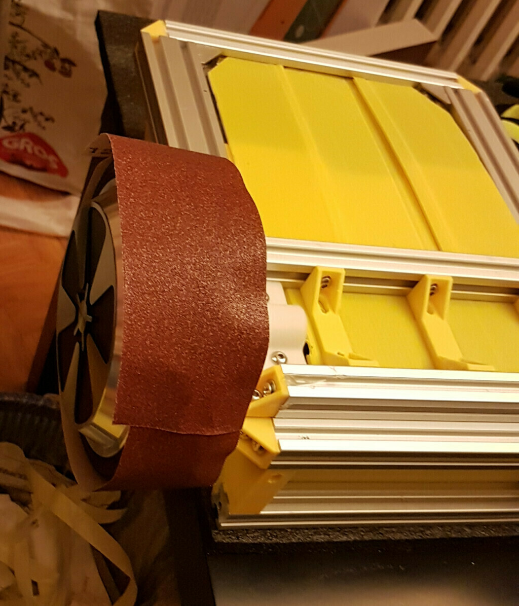
Yep I did that and it was working flawlessly.
With the frame shaping out nicely it was time to consider how to fill the empty spaces in the frame. The aluminium extrusion would provide the main body so I was quite free to choose how to fill the voids and so I experimented with some scrap corrugated plastic that I had around (I cut some pieces from the boxes contaning fresh vegetables) and they matched perfectly for what I had in mind, as a bouns point they are very easy to fold and cut, they also matched the yellow-gray-black color scheme that I had in mind. A perfect fit!
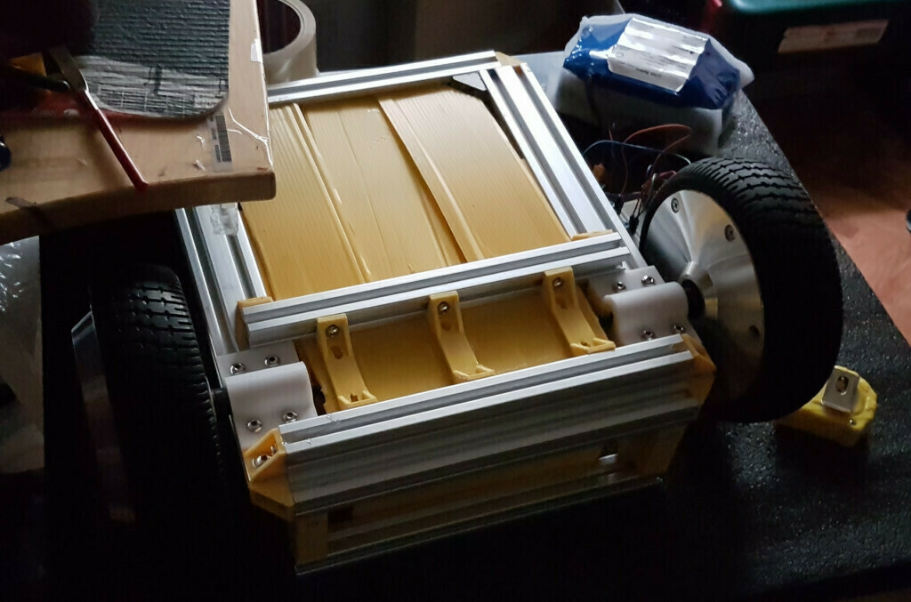
At this point I wondered how many segments for the threads I needed to print in order to get the distance of the idlers wheel right and also to get just the right tension on the threads. It turned out that it was quite impossible to judge in detail so once I ball-parked a distance, I left the proper fine-adjustment to be made on a later moment. I was also reaching the point that I feared the most, having to wait weeks just to print the wheels and the thread segments. Being able to rapid prototype pieces is a lot of fun, getting to the final iteration of that piece and having to wait weeks to complete the build is not.
so shall I entertain you with some photos in the meanwhile? ..
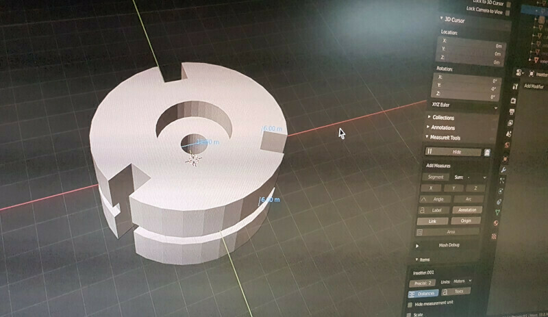
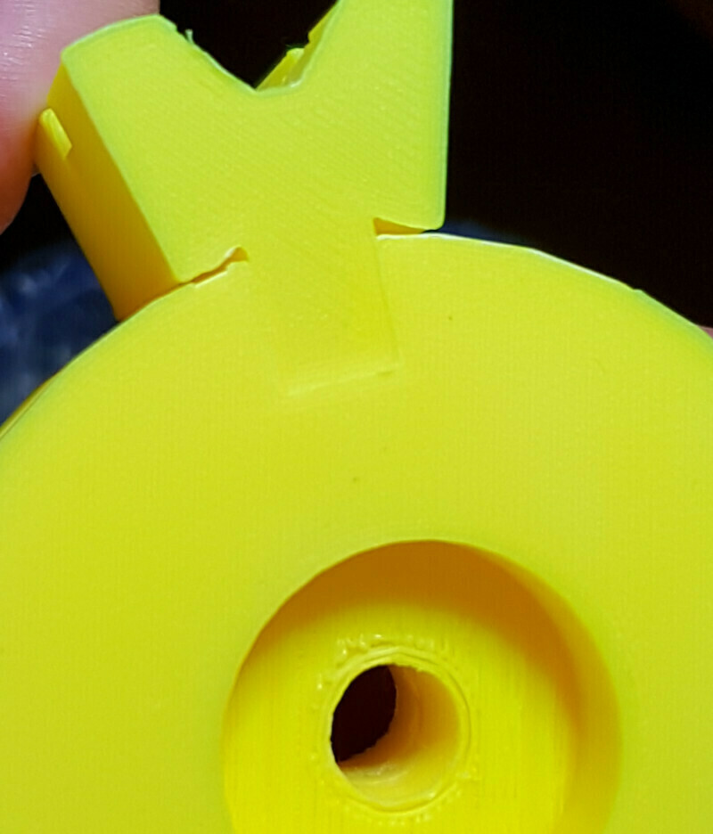
When I prototype some pieces, especially pieces that interlocks each other, I usually cut a section and print just the parts that need to test for fitting, in order to save print time and material. Blender makes this easy if you have a grasp of what you want to achieve, you can just create a mesh that would contain your section, then use boolean modifiers to intersect your piece. voilà!
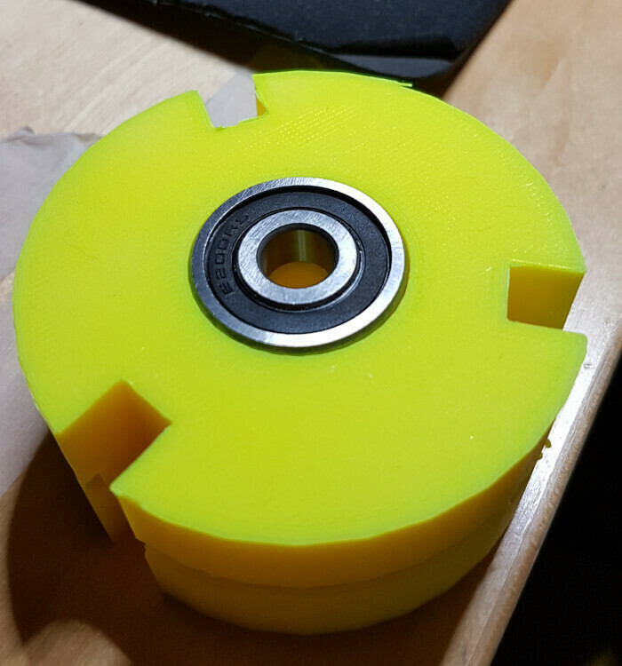
With the interlocking mechanism got right, I printed the idler wheel. Three pieces (120° each of the wheel), and the inner core. Here’s a pic of the final idler wheel
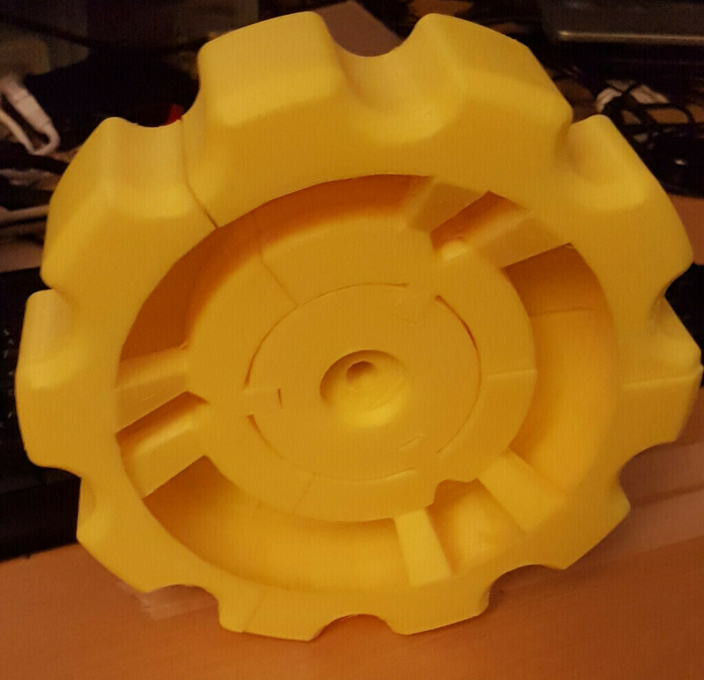
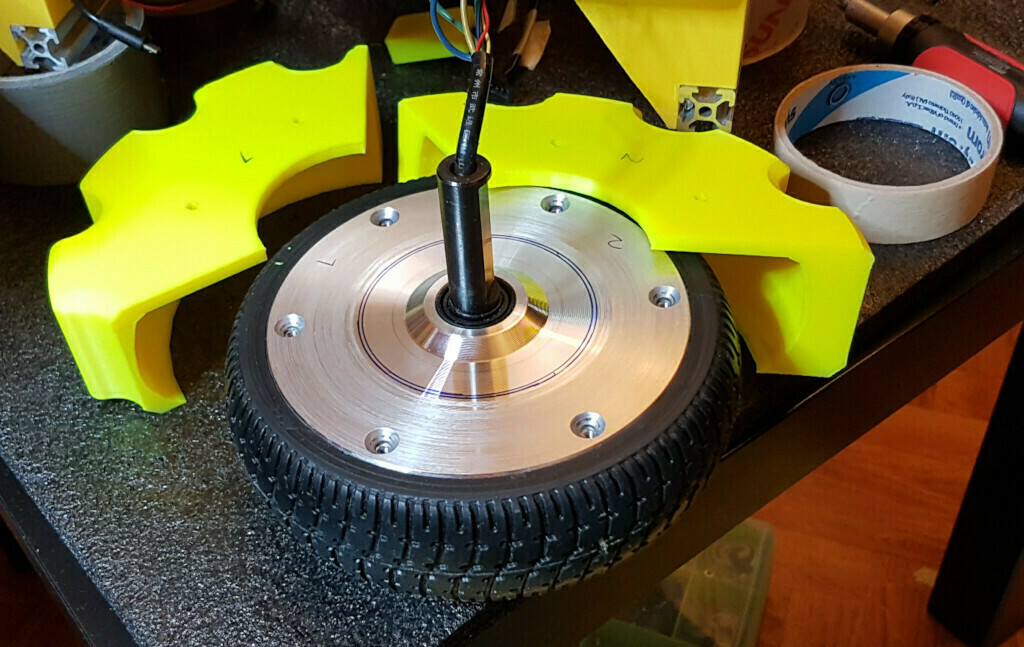
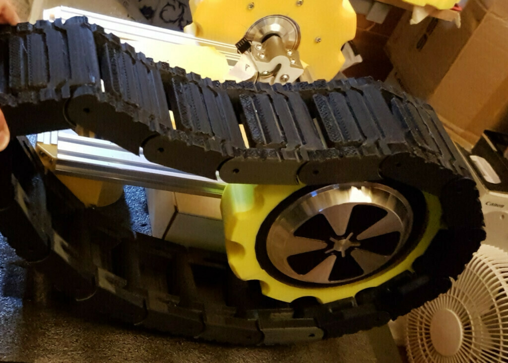
Let’s just not forget about the most important wheels, the driving ones. Here’s a picture of the gear that I attached on top of them. I had quite a solution for making the holes needed to attach the gear to the wheel: I used some masking tape, attached it to the wheel and marked the holes, then I attached the masking tape on the gears and drilled the holes. Sound complicated but .. well, no, it was complicated. But it worked quite well.
and so I managed to finally attach the gears on the driving wheel. Probably the most difficult part (mechanically wise) of the build.
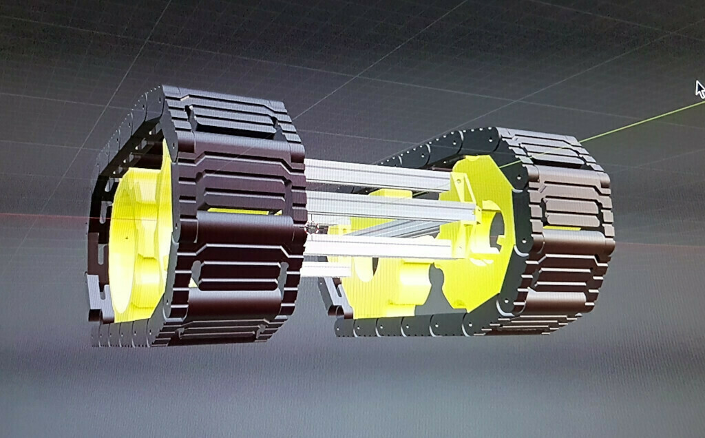
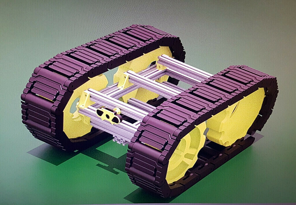
Back in Blender, I finally gave myself a bit of relax with some renderings, but first I had to get some of the pieces lined up with all the real-world measurements that I now had..
It was then time for the most boring part. Printing, cleaning, sanding the thread links. I had to print 34 of them, clocking at 4h54mins each one. Yes, that was very, very boring. A tight schedule to start each print job was needed in order to make this project coexist with, you know, my regular life. But then ..
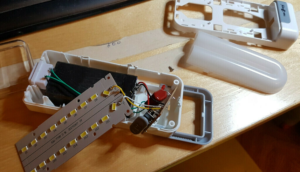
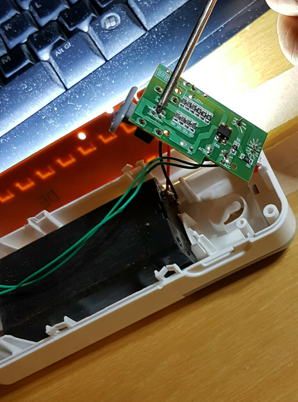
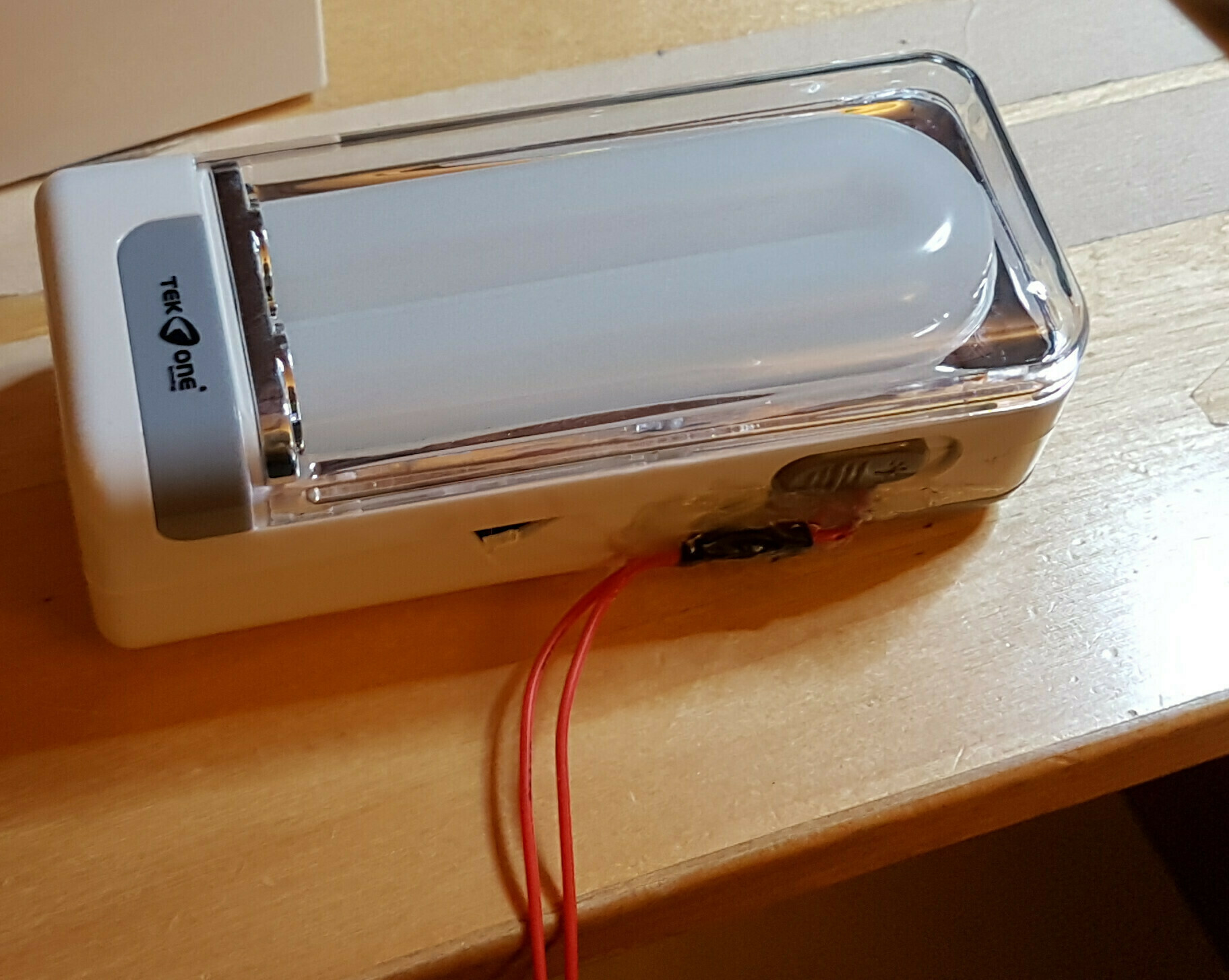
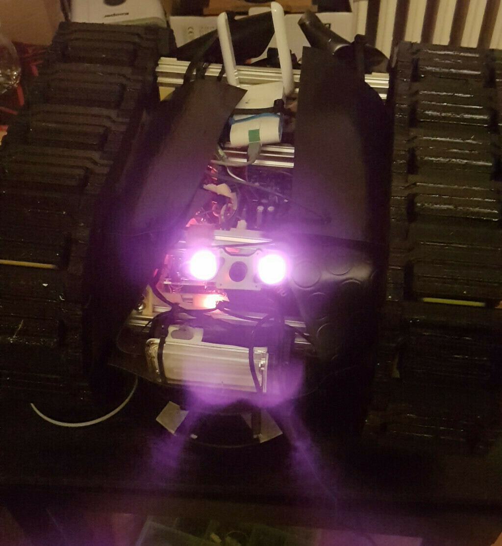
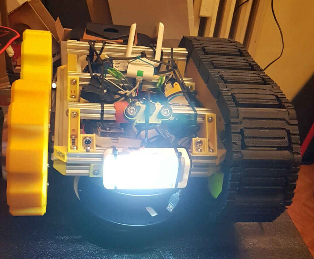
While I was still printing the threads I kept experimenting in the electrical/electronic part of the build. I settled using a relay connected to the raspberry to turn on/off the hoveboard board and sice I used a 2-channel relay I hade a spare relay. I made a trip to my local all-selling chinese shop for some hardware bits and I then spotted a nice emergency lamp. Could I resist a self-contained led lamp that already had a battery, charger and whatever for around 6e? of course not. I bought the lamp and ran back home to disassemble it.
Just bear with me, I had to keep me busy when printing the threads links. Frankly it was the longest print job (combined) of my entire life, even longer than the print jobs for my HexapodMG (I’ll write a build log for this little robot in the future. for now enjoy his walking)
also nothing says danger like yellow-and-black color scheme. well a terrifying hexapod running to you helps too.
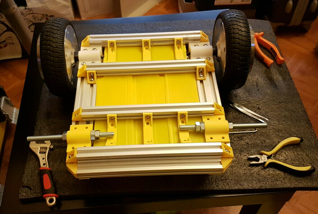
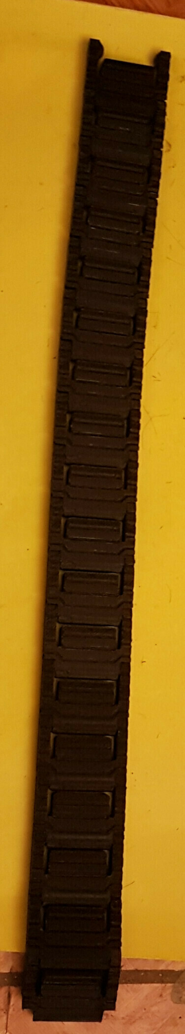
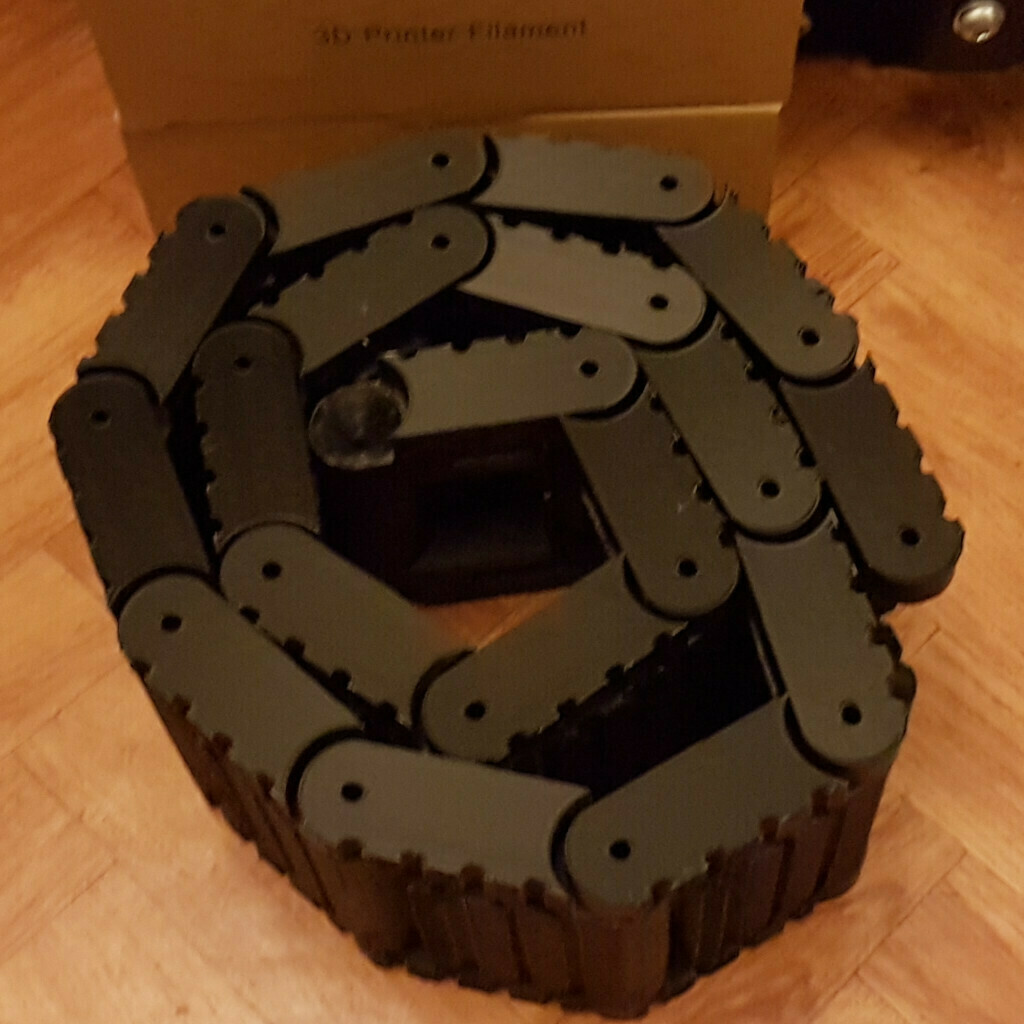
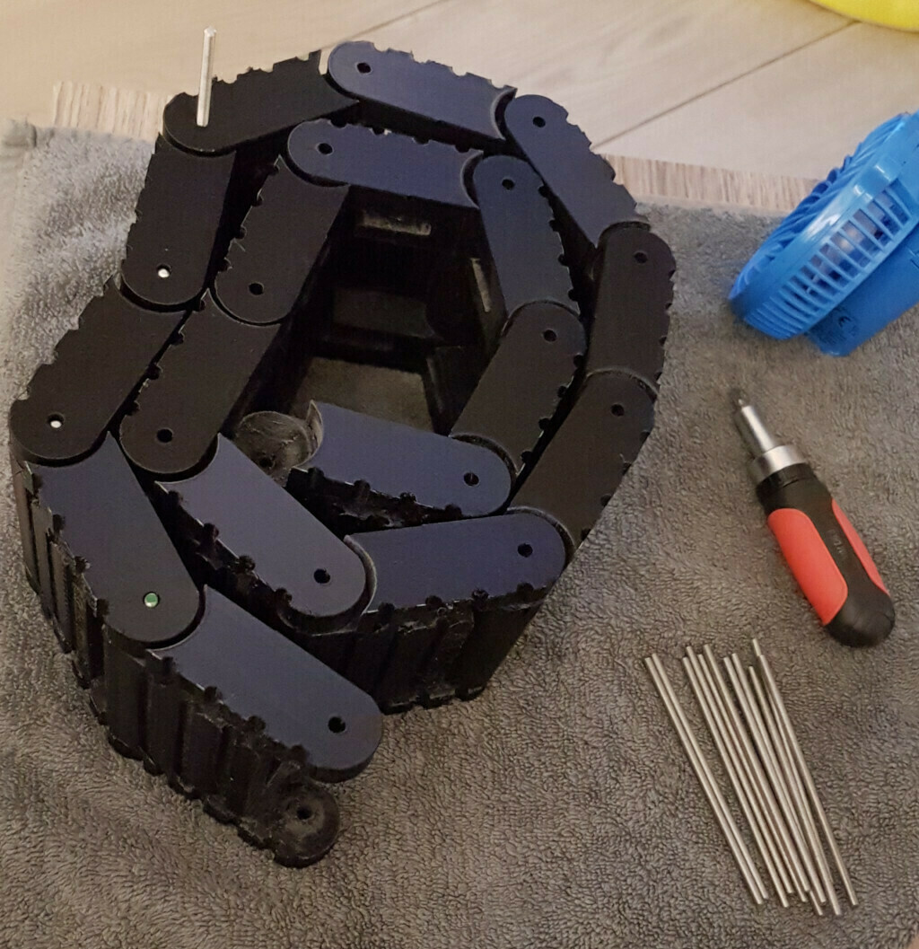
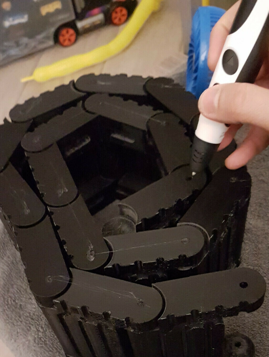
I somehow managed to print all the thread links. I also inserted some 4mm threaded rod between each link to make it more resistant and closed the holes with a bit of PLA and a 3d pen. Just like this
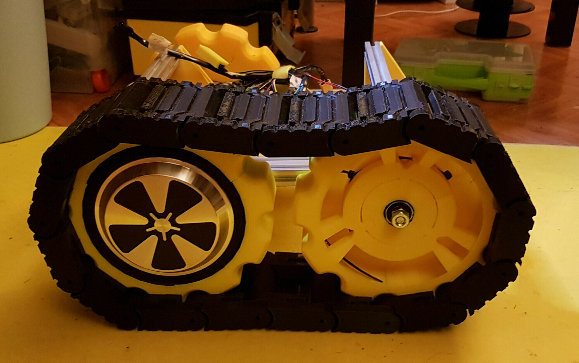
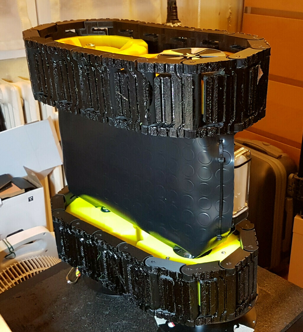
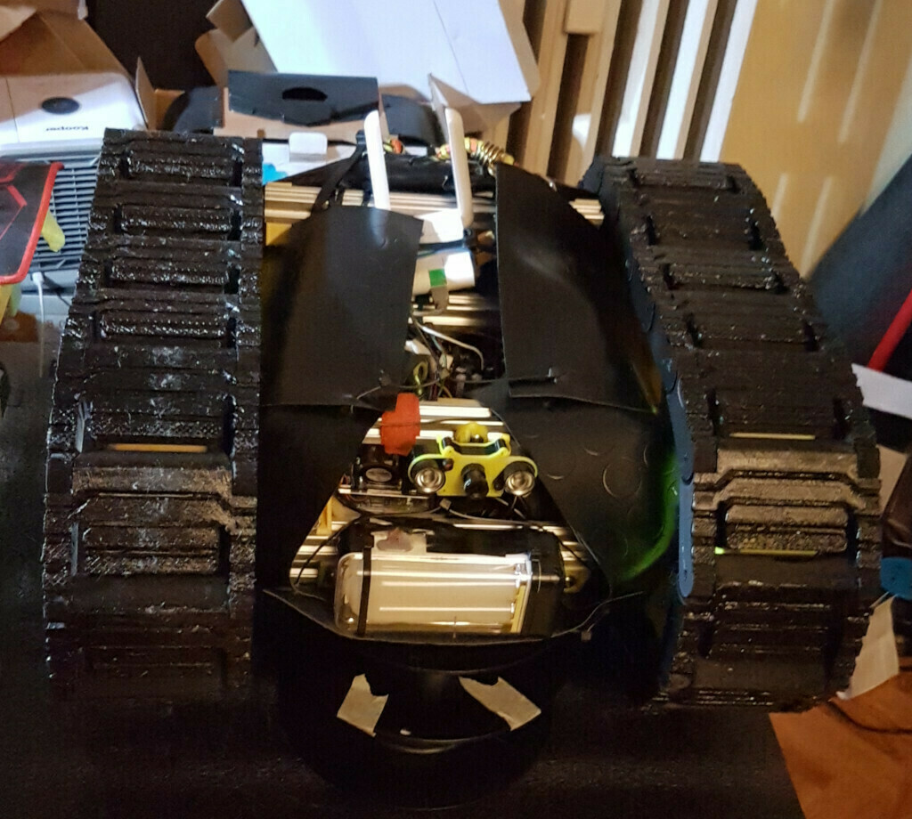
With the threads done, it was time for the final part of the assembly. Of course “final” is a bit ephemeral since it would be most appropriate to say final, for now. I need to take this tank out in order to observe how it performs in different terrains to make some small adjustment and to print a proper enclosure, but for now I managed to cover it with a piece of anti slipper pad that I found, you guessed it, at my local all-selling chinese shop. and so, enjoy the current build of my tank, weighing in at around 15kg! It was a very fun build and I’ll upload some videos as well as the models, electronic schematics, details of the software part and bulding tips like the rubberized threads if there’s interest. see you! As promised some tips for Blender users in the end section, as well as some special thanks.
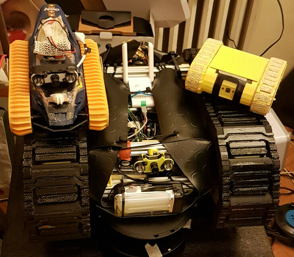
some other rovers I’ve made so far. There’s also a fourth one somewhere.
Luckily for its little brothers, I didn’t have to take pieces from them, they only provided software bits
All Aboard, the tank is leaving!
Thank you for reading this far.
Special thanks to the awesome people at the bipropellant firmware github, especially to btsimonh, EmanuelFeru, sderr.
Thank you guys!
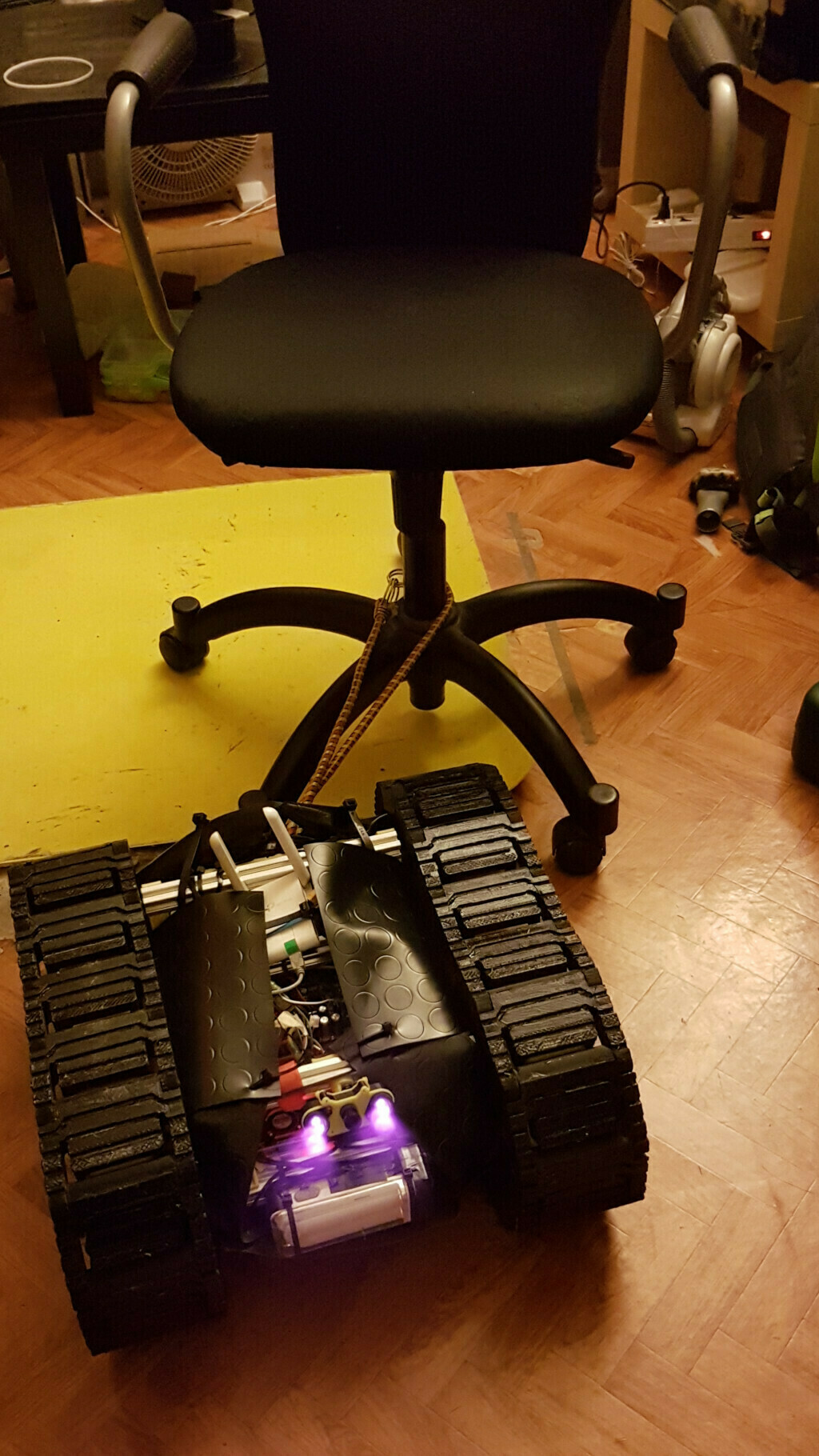
Enjoy a small video of the tank in the office seat tow test, more videos and expanded build log coming soon. check back later!
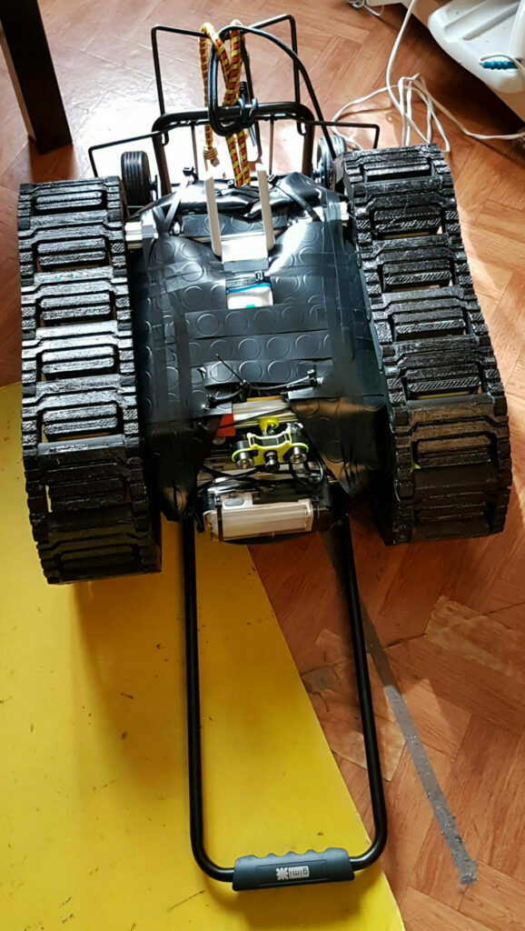
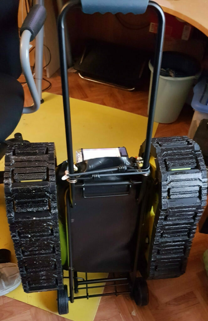
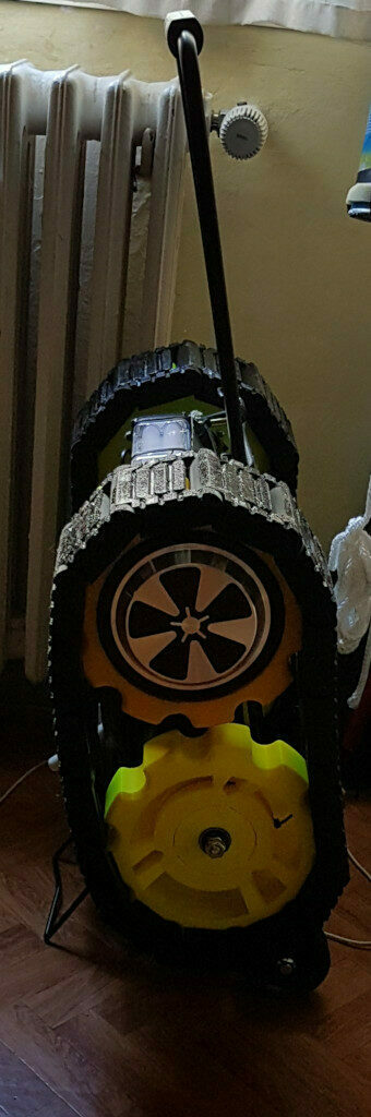
With the tank almost splash proof, it is now time to take it out and carefully observe how it moves, climbs, tow and look for deficiencies and think about ways to improve it. All good and stuff, but my back begs for mercy. This thing is quite heavy to move. Sure it can be dragged using the elastic cord to lift it (a better one is on the way, by the way), however the tank threads aren’t that good when dragged in uneven terrain since in this position only some segments are kept in contact with the terrain, so wheels are the best solution for easily drag it. Guess what? It was time to pay a visit to the usual all-selling chinese shop. It never disappoints me. I came back with this kind of trolley which fits perfectly.
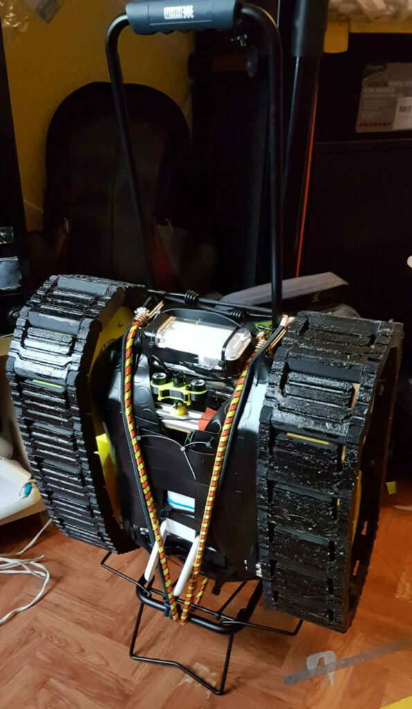
It also provide a very nice way to deploy it as I only have to tilt it, then the tank is free to move.
This trolley also reminded me that there’s still a long way to go since it provided a preview for an entry of the list of the things still todo, that is the back wheels.
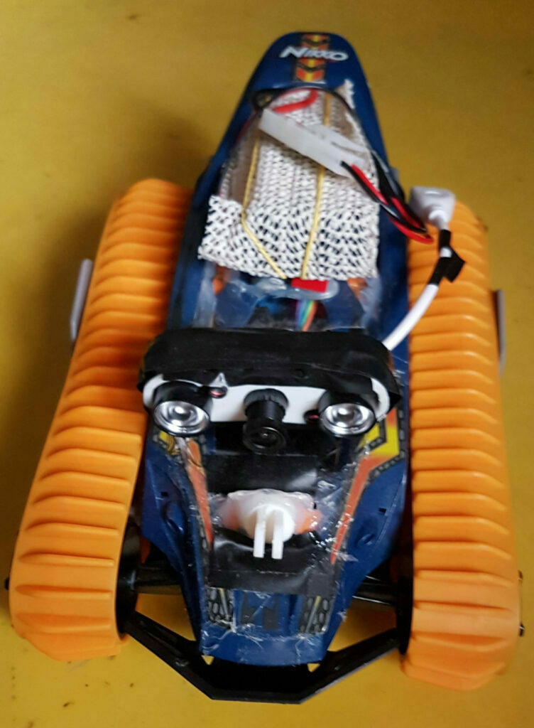
I mentioned earlier that I had the idea for a search and rescue rover for quite a while and I made some rover before, tackling each time a different problem for good. A previous rover that I made (I’ll write a build log in the future) showed some difficulties climbing steep slopes. That is a nicer way to say that it just rolled down in the most spectacular way. Thinking about a solution for this and while I was scavenging for parts, I came up with some roller bearings repurposed from the same cheap chinese delta kit for a 3d printer which I cannibalized for my custom made “Ragnetto”.
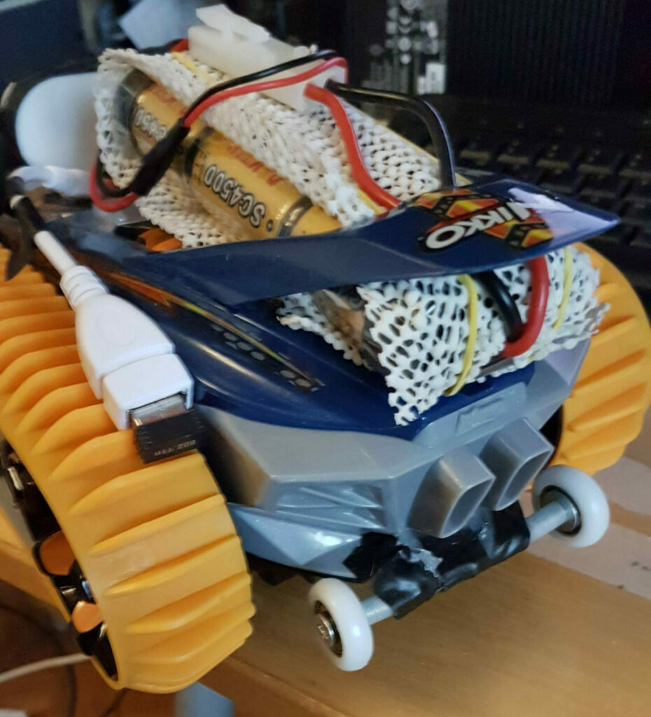
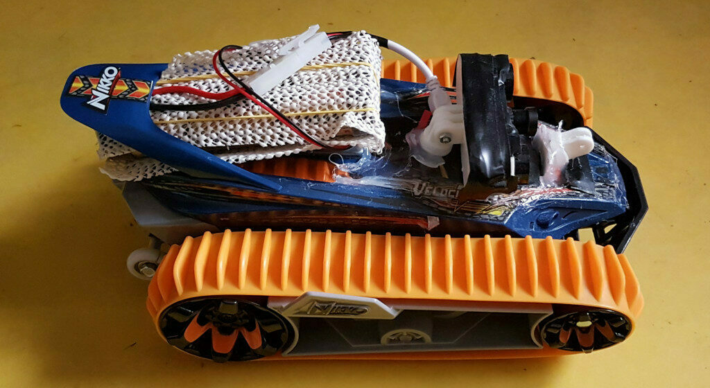
.. and while we are at it, enjoy some photos of this little rover. It is made out of a hacked Nikko Velocitrax which provided the best bang-for-robotics-buck of my life, since it already had a good gear ratio, enough volume (once I removed tons of plastic) to fit a Raspberry Pi Zero W, a L298N Dual H Bridge (with free space for a heatsink too!), buck converter etc. If you’re interested in hacking toys / building robots, this is a very nice toy to start with.
Back in the current build, here’s a pic of the trolley that reminded me the item in the todo list
Tips for blender users
As I have written above, when it comes to modeling thing for machining / 3d printing, maybe blender is not the most appropriate tool. Still, i prefer Blender above other proper CADs so I’m going to show some tips on how I got into that. Note that all the following tips are for Blender 2.80. I’m still rewiring the brain for all the changes that made their way into this version and some of them I’m still struggling with, but it will get better with time I think. Let’s start
MeasureIt addon is your best friend
The most useful addon for turning Blender into a CAD is the MeasureIt addon. Enable it the usual way: Edit menu->Preferences->Add-Ons->3D View: MeasureIt (Tick the checkbox). After that enable it in the Layout/Modeling/Sculpting workspace by pressing the ‘n’ key, then in the ‘view’ pane select MeasureIt toosl. Press the “Play” icon to show it or hide it. Usage is simple, just select the items you want to measure (say, the distance between two vertexes) then click “Segment”. You can customize the colors, size, position of the label that contains the measurement. Note that this is quite different from the ruler tool that was added in Blender 2.80 as the ruler tool can be snapped to vertexes and will provide a measurement, but if the geometry of the meshes change it won’t be automatically updated, the measure it measure instead updates in realtime when you work on the mesh. Also, it is possible to show edge lenght without the MeasureIt addon, however that view option is just a mess since it measure every distance from all the vertexes of your mesh, it can give you quite an headache and also slows blender down when the geometry increases.
Learn every snapping method blender has to offer
To make up for the missing operations on blender vs other CADs a general workaround is to snap objects, vertexes, edge and whatever to other items. Aligning a camera mount on a 2020 extrusion model? too easy. just choose “vertex” snapping method (the icons to the right of the magnet) and enable the “closest” option. The enable/disable snapping with the magnet icon. I prefer to leave the snapping disabled and use it only when I need by modifying the operation I’m doing (say, grabbing an item) by pressing CTRL on the keyboard. There are a lot of snapping method and each one is useful in a particular scenario so it is a good idea to learn them all. Once you learn how to snap anything on anything, you’ll feel like there’s nothing you can’t do in the 3d space.
Learn to move objects using constraints
Blender has a powerful way to restrict movements/rotations/operations on specific axes. Say you want to make an object taller but want to keep its size in the x/y plane. Just scale the object (keyboard s) then tell blender to scale only in the z axis by just pressing, you guessed it, z on the keyboard. voilà! It even work in a complement-way, if you want to exclude an axis for the scale operation, press shift+the axis you want to exlude (say, shift+y) while you perform an operation. Simple but powerful. You can also apply an axis as a constraint by clicking the middle mouse button when performing a transform.
Learn how transforms act based on the orientations
Blender transfroms such as scale, rotation etc act differently depending on the type of orientations you choose. In the upper menu, click the three axis icon to change the orientations, there are a lot of options available such as Global/Local/Normals and so on. Each one is useful and it is a good idea to learn them all, a lot of time something that seems hard to do can simply be accomplished by changing the orientations, for example in times when you need to slide an object along its normal.
More tips coming soon..
References
Bipropellant hoverboard firmware https://github.com/bipropellant/bipropellant-hoverboard-firmware
hoverboard-firmware-hack https://github.com/NiklasFauth/hoverboard-firmware-hack/blob/master/README.md
hoverboard motor clamp https://www.thingiverse.com/thing:2991697